MotionCapture Plugin
Function 1: Recording and Displaying Marker Trajectories
This feature records and displays the position and orientation of "PassiveMarker" devices as time-series data. This section explains how to record and display passive marker trajectories using the Motion Capture Controller item.
Creating and Configuring the Motion Capture Controller Item
First, generate the Motion Capture Controller item, which serves as the core component for the recording. Select File > New > Motion Capture Controller from the main menu. Place the generated Motion Capture Controller item as a child of the target Body item.
Configuring Passive Markers
The Motion Capture Controller records the position and orientation of passive markers defined on the body. Similar to cameras or lights, a passive marker is described under the elements of any link. Below is an example of a passive marker description:
-
  type: PassiveMarker
  name: RedMarker
  translation: [ 0.0, 0.0, 0.3 ]
  rotation: [ 0, 1, 0, -90 ]
  radius: 0.1
  color: [ 1.0, 0.0, 0.0 ]
  transparency: 0.3
Details for each key are as follows:
Parameter |
Default Value |
Unit |
Meaning |
|---|---|---|---|
radius |
1.0 |
m |
Specifies the radius of the passive marker. |
color |
1.0, 0.0, 0.0 |
- |
Specifies the color of the passive marker in RGB. |
transparency |
0.0 |
- |
Specifies the transparency level of the passive marker. |
symbol |
true |
- |
Toggles the visibility of the symbol representing the passive marker. |
Running the Simulation
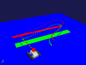
Run the simulation as usual from the Simulation Bar. Once the simulation is finished, the trajectory of the passive marker will be displayed in the Scene View.
The trajectory is recorded as a Point Set item and is automatically registered in the Item Tree view as a child of the Motion Capture Controller item. You can toggle the visibility of the trajectory by checking or unchecking the Point Set item.
Function 2: Recording and Displaying Collisions
The Motion Capture item records the occurrence of collisions simultaneously with the passive marker trajectories. This section explains how to record collisions using the Motion Capture feature.
Creating and Configuring the Motion Capture Item
Generate the Motion Capture item, which acts as the core component for the recording. If a Motion Capture item is already placed as a child of the target body, this step is not necessary.
Select File > New > Motion Capture from the main menu. Place the generated Motion Capture item as a child item of the target body.
Running the Simulation
Run the simulation as usual from the Simulation Bar. Once the simulation starts, a child item named "CollisionSeq-<date>," which records the presence or absence of collisions, will be registered in the Item Tree view under the "Motion" group.
Note: <date> represents a timestamp suffix.
Exporting Collision Data to a File
Follow these steps to export the recorded collision data to a file:
Select the item "Collision-<date>" that was automatically generated after the simulation.
Select File > Export Selected Items from the main menu.
Enter a filename in the dialog box and click the Save button.
Displaying Collision Data in a Graph
You can display the recorded collision data in a graph by following these steps:
Select View > Show View > Multi Value Seq from the main menu.
Select the item "Collision-<date>" that you wish to graph.
Select the numbers (jointId) displayed on the left side of the Multi Value Seq view.
Function 3: Recording Joystick Status
The Motion Capture item records the joystick status simultaneously with the passive marker trajectories. This section explains how to record the joystick status.
Configuring Joystick Status Recording
First, generate the Motion Capture item, which serves as the core component for the recording. If a Motion Capture item is already placed as a child of the target body, this step is not necessary.
Select File > New > Motion Capture from the main menu. Place the generated Motion Capture item as a child item of the target body.
Next, modify the Motion Capture item settings as follows:
Select MotionCapture in the Item Tree view.
In the Property View, specify the device name for the desired joystick under Device.
Details for the Motion Capture item settings are as follows:
Parameter |
Default Value |
Unit |
Meaning |
|---|---|---|---|
Device |
/dev/input/js0 |
- |
Specifies the device name of the joystick. |
Running the Simulation
Run the simulation as usual from the Simulation Bar. Once the simulation starts, a child item named "JoystickSeq-<date>," which records the joystick status, will be registered in the Item Tree view under the "Motion" group.
Note: <date> represents a timestamp suffix.
Exporting Joystick Status to a File
Follow these steps to export the recorded joystick status to a file:
Select the item "JoystickSeq-<date>" that was automatically generated after the simulation.
Select File > Export Selected Items from the main menu.
Enter a filename in the dialog box and click the Save button.
In the exported file, the joystick status is recorded in the order of All Axes (sticks) followed by All Buttons. (For example, if using a joystick with 8 axes and 13 buttons, the data is recorded in the order: Axis-0, Axis-1, ..., Axis-7, Button-0, Button-1, ..., Button-12.)
Displaying Joystick Status in a Graph
You can display the recorded joystick status in a graph by following these steps:
Select View > Show View > Multi Value Seq from the main menu.
Select the item "JoystickSeq-<date>" that you wish to graph.
Select the numbers displayed on the left side of the Multi Value Seq view.
The numbers on the left side of the Multi Value Seq view correspond to each stick and button on the joystick, assigned in the order of All Axes followed by All Buttons. (For example, with 8 axes and 13 buttons, numbers 0 through 20 are assigned. 0 to 7 represent the axes, and 8 to 20 represent the buttons.)